This Godot Engine shader tutorial will take you step by step towards creating a single plane water shader in Godot 4 that won’t send players packing. We’ll cover setting up the water mesh, creating the shader, and coding the graphical qualities like albedo, roughtness, and normal. You’ll also be able to take advantage of setting shader variables, animating the water, and adding fresnel to give it an extra pinch of realism.
Full video tutorial is also available via the Youtube channel.
Setting Up the Godot 4 Project
To get started, open Godot 4 and create a New Project. We’ll be using the Forward+ renderer so make sure that is selected.
Before we jump into coding, we need to setup our workspace a bit. It’s always good to stay as organized as possible so we will create the following folders in the Filesystem Tab: Scenes, Shaders, Resources.
We will be starting with just two scenes: a map scene and a water plane scene. The water plane scene will contain just our basic quad mesh plane, which we can then insert into the larger map scene. Create two scenes (Map.tscn and WaterPlane.tscn) and place them into the Scenes folder. The Map.tscn will use a 3D node as a parent and set the WaterPlane.tscn parent node to a MeshInstance3D node.
Setting Up the Water Plane Scene
Open the WaterPlane scene and click on the MeshInstance3D node. To the right is the inspector tab that holds all the node information.
- Find the MeshInstance3D title
- Look for the Mesh field and click on the dropdown
- Select New QuadMesh
We now have a plane mesh in our viewport area. We’ll need to adjust it a bit so it’s ready for our shader.
- Click on the mesh dropdown to open up the mesh properties
- Set the size to 1 m x 1 m
- Subdivide the width and depth by 200
- Set the orientation to Face Y
Setting the size to 1m is small BUT we’ll be making the plane scalable through the shader. The subdivision really determines how detailed the plane will be and that can be scaled according to the amount detail you need. The orientation will set the plane facing upwards.
Next we’ll create the Shader for our water plane mesh.
- Look for the Surface Material Override and click on the dropdown
- Select New ShaderMaterial
- Click on the Material and click on the Shader dropdown, creating a New Shader
We’ll name this Water.gdshader and use the Spatial Mode. Then save both the parent ShaderMaterial and place both in the Shaders folder.
Coding the Water Shader
With the project set, we’re ready to start coding our water shader. Godot provides a shading language based on OpenGL Shading Language (GLSL) and while it may look similar to GDScript, there are differences in language and syntax.
First, open the Water.gdshader file. This will bring up the Shader Editor at the bottom of the screen and show you the barebones of the shader script.
shader_type spatial;
void fragment() {
	// Place fragment code here.
}
shader_type sets our shader type (spatial) and void fragment() is where we can run code for the pixel shader.
Within the pixel shader we can set the usual values like ALBEDO, METALLIC, ROUGHNESS.
We’ll add our first code into the fragment function to turn the plane mesh black.
void fragment() {
	ALBEDO = vec3(0,0,0);
}
Now we can keep our vector value in the pixel shader but it would be much easier if we could edit that value from the editor or from GDScript. To do that, we can use uniform variables. By adding a uniform variable albedo, we can set the color in the editor and pass that variable to the pixel shader.
shader_type spatial;

uniform vec3 albedo : source_color;

void fragment() {
	ALBEDO = albedo;
}
With our code set, we can click on the Surface Material Override of our mesh and find the Shader Parameters tab, where all of our uniform variables will show.
- Set the Albedo color to 00526e
- Repeat the same variable and parameter process for both Metallic and Roughness
shader_type spatial;

uniform vec3 albedo : source_color;
uniform float metallic : hint_range(0.0, 1.0) = 0;
uniform float roughness : hint_range(0.0, 1.0) = 0.02;

void fragment() {
	ALBEDO = albedo;
	METALLIC = metallic;
	ROUGHNESS = roughness;
}
We’ve added hint_range() that will set the range of values possible for the variable as well as a default value.
Adding Normal Maps
With our ALBEDO, METALLIC, ROUGHNESS values set, we can move to the more involved process of adding normal maps. Normal maps are a great way to add cheap depth and texturing to a material without adding to the geometry. We’ll use two normal maps to simulate some surface movement and texturing for our water plane.
Let’s add two more uniform variables to our code, only this time we’ll use a sampler2D texture.
uniform vec3 albedo : source_color;
uniform float metallic : hint_range(0.0, 1.0) = 0;
uniform float roughness : hint_range(0.0, 1.0) = 0.02;
uniform sampler2D texture_normal;
uniform sampler2D texture_normal2;
Let’s get our first normal texture up and running.
- Go to the Shader Parameters of the mesh Surface Material Override
- Find Texture Normal and click on the dropdown
- Click New NoiseTexture2D
- Click on the dropdown to open it
- Find Noise and click on that dropdown and choose New FastNoiseLite
The Godot Engine comes with a built-in noise generation via FastNoiseLite and we’ll use it to generate some water-like noise for our material.
For our settings we’ll go with Perlin for our Noise Type and for our Fractal Type, we’ll go with Ridged. Then set Seamless to true, As Normal Map to true, and set the Bump Strength to 1.5.
With our noise texture ready, we can reference it in our shader code.
shader_type spatial;

uniform vec3 albedo : source_color;
uniform float metallic : hint_range(0.0, 1.0) = 0;
uniform float roughness : hint_range(0.0, 1.0) = 0.02;
uniform sampler2D texture_normal;
uniform sampler2D texture_normal2;

void fragment() {
	vec3 normal = texture(texture_normal,UV).rgb;

	ALBEDO = albedo;
	METALLIC = metallic;
	ROUGHNESS = roughness;
	NORMAL_MAP = normal;
}
(IMAGE)
To get the noise texture we must use texture() and UV to get the texture and coordinates of our noise.
We can create a second noise texture just like the first and then interpolate between the two textures to mix them into one. To do that, we’ll create a new variable normal_blend that will mix both normal maps and then pass that variable to our NORMAL_MAP value.
Animating the Normal Maps
Static water doesn’t look too great, so we need add some movement to our shader. One way we can do that is to animate the normal maps we just added. We’ll need to add some more variables to control the rate of movement and the direction of movement. Then we can use the built-in TIME function to add to the UV offset each frame or tick.
First let’s add our new uniform variables.
uniform vec3 albedo : source_color;
uniform float metallic : hint_range(0.0, 1.0) = 0;
uniform float roughness : hint_range(0.0, 1.0) = 0.02;
uniform sampler2D texture_normal;
uniform sampler2D texture_normal2;
uniform vec2 wave_direction = vec2(2.0,0.0);
uniform vec2 wave_2_direction = vec2(0.0,1.0);
uniform float time_scale : hint_range(0.0, 0.2, 0.005) = 0.025;
Then add two variables within the pixel shader for to calcuate the time multiplied by the wave direction multiplied by the time_scale.
// Time calculations for wave (normal map) movement
vec2 time = (TIME * wave_direction) * time_scale;
vec2 time2 = (TIME * wave_direction2) * time_scale;
// Blend normal maps into one
vec3 normal_blend = mix(texture(texture_normal,UV).rgb, texture(texture_normal2,UV).rgb, 0.5);
With our variables ready, we can add our movement time and time variables to our UV values in the normal_blend variable.
vec3 normal_blend = mix(texture(texture_normal,UV + time).rgb, texture(texture_normal2,UV + time2).rgb, 0.5);
We now have some movement in our water shader! This may be enough for your purposes BUT we can do some more with our shader to bring the water up a few notches.
More Advanced Shader Features
FRESNEL
The first graphical boost we can give our water is to add a fresnel effect to our overall albedo. Fresnel will adjust the color of albedo depending on the angle the camera is viewing the mesh. This effect occurs naturally and can be replicated relatively easily in our code.
The first lines of code we need are another uniform variable for our second albedo color and a fresnel function that we will run in the pixel shader.
uniform vec3 albedo2 : source_color;
And then our new fresnel() function.
....
uniform float time_scale : hint_range(0.0, 0.2, 0.005) = 0.025; // Rate of movement multiplied by TIME

float fresnel(float amount, vec3 normal, vec3 view)
{
	return pow((1.0 - clamp(dot(normalize(normal), normalize(view)), 0.0, 1.0 )), amount);
}

void fragment() {
....
You might notice the declared variables in the function. These are called hints and are part of Godot’s static typing feature. Using typed hints is a good practice as it sets what values must be used within the function and make it easier for the editor to suggest code.
Next, you need to add another variable in the pixel shader that will run our fresnel function and then interpolate between our albedo and albedo2 values using our fresnel value as the alpha, and finally passing the result to our ALBEDO value.
// Blend normal maps into one
vec3 normal_blend = mix(texture(texture_normal,UV + time).rgb, texture(texture_normal2,UV + time2).rgb, 0.5);
// Calculate Fresnel
float fresnel = fresnel(5.0, NORMAL, VIEW);
vec3 surface_color = mix(albedo, albedo2, fresnel); // Interpolate albedo values by frensel

ALBEDO = surface_color;
METALLIC = metallic;
You should be able to play with the Albedo 2 color value in the editor and come up with some interesting color combinations. For the example, we can use 0079c3.
VERTEX DISPLACEMENT AND SCALING
We have faked texture and depth with our normal maps but we create actually height with our shader by adjusting the vertices our mesh with noise.
But we can’t do this is the pixel shader, we need to use the vertex shader. This occurs in a different function that you can add after our uniform variables and before the fragment().
void vertex() {
	....
}
For our vertex displacement, we’ll need three more uniform variables: wave (sampler2d), noise_scale, and height_scale.
uniform sampler2D wave;
uniform sampler2D texture_normal;
uniform sampler2D texture_normal2;
uniform vec2 wave_direction = vec2(2.0,0.0);
uniform vec2 wave_2_direction = vec2(0.0,1.0);
uniform float time_scale : hint_range(0.0, 0.2, 0.005) = 0.025;
uniform float noise_scale = 10.0;
uniform float height_scale = 0.15;
We also want to make the mesh and shader scalable…meaning the normal map and vertex displacement should occur via world position rather than the mesh UV. This will allow us to make the mesh as big as we want and not have to worry about any stretching or scaling issues.
To do that, we need a NEW kind of variable that can carry values from the vertex shader to the pixel shader called varying variables.
We’ll add two of these variables after our uniforms variables.
varying float height;
varying vec3 world_pos;
Next move to the vertex shader where we can set the world_pos for each vertex of our mesh with the following code:
void vertex() {
	world_pos = (MODEL_MATRIX * vec4(VERTEX, 1.0)).xyz;
}
The next two lines will take our noise texture and grab the R value (0 to 1) at the location of each vertex. Then that height value is multiplied by the height_scale and added the Y value of the vertex to raise or lower it’s height.
void vertex() {
	world_pos = (MODEL_MATRIX * vec4(VERTEX, 1.0)).xyz;
	height = texture(wave, world_pos.xz / noise_scale + TIME * time_scale).r;
	VERTEX.y += height * height_scale;
}
Because we can also grab the TIME value, we animate it just like we did with the normal maps. With our code set, we just need to generate our noise texture in the Shader Parameters. Be sure to set the NoiseTexture2D to seamless.
Additionally, with our world_pos variable, we can swap out the UV variable in our normal_blend vector so that our normal maps also scale properly.
With our new vector displacement, you may notice dark spots showing on the mesh. To get rid of these, simply turn off Cast Shadow in the Geometry tab of the mesh inspector.
DEPTH FADE
Another shader trick we can add is a depth fade so that the water surface color adjusts to how close the mesh is to other meshes beneath it. This replicates how light scatters when passing through water.
To achieve the effect, we’ll need to add some more code to our shader and adjust some of the existing code. First we’ll add some more uniform variables:
uniform vec4 color_deep : source_color;
uniform vec4 color_shallow : source_color;
uniform float beers_law = 2.0;
uniform float depth_offset = -0.75;
These will allow us to set our deep (1b4b54) and shallow water (008da6) colors and the application of Beer’s law which deals with the attenuation of light per the properties of the material through which the light is travelling, in this case water. Your beers_law and depth_offset value may be adjusted depending on the effect you want and the overall depth of the water.
Next, we can add the following code to the top of our pixel shader function that will get a depth texture from the viewport and apply a blend and coloration of the depth gradient.
void fragment() {
	float depth_texture = texture(DEPTH_TEXTURE, SCREEN_UV).r * 2.0 - 1.0;
	float depth = PROJECTION_MATRIX[3][2] / (depth_texture + PROJECTION_MATRIX[2][2]);
	float depth_blend = exp((depth+VERTEX.z + depth_offset) * -beers_law);
	depth_blend = clamp(1.0 - depth_blend, 0.0, 1.0);
	float depth_blend_power = clamp(pow(depth_blend, 2.5), 0.0, 1.0);

	vec3 screen_color = textureLod(SCREEN_TEXTURE, SCREEN_UV, depth_blend_power * 2.5).rgb;
	vec3 depth_color = mix(color_shallow.rgb, color_deep.rgb, depth_blend_power);
	vec3 color = mix(screen_color * depth_color, depth_color * 0.25, depth_blend_power * 0.5);
Finally, we need to swap out our ALBEDO value again, this time incorporating our new depth colors.
ALBEDO = mix(surface_color, color, 0.75);
You should now be able to go to the Map.tscn, add your water plane if you haven’t already and add a basic mesh to see the color change depending on the depth of the object.
EDGE DETECTION
Another use for depth is find where the mesh is closest to or touching another mesh. By clamping a range of values where the mesh is closest, we separate those pixels and adjust their color independently, giving the effect of a foam edge. The overall look of this effect will largely depend on their artistic needs of your scene, but this offers one way to achieve the effect.
We’ll first need to add four more uniform variables and a new function called edge().
The values of these variables will again depend on the look you’re trying to achieve.
uniform float edge_scale = 0.1;
uniform float near = 0.5;
uniform float far = 100.0;
uniform vec3 edge_color : source_color;
And our new function:
...
float fresnel(float amount, vec3 normal, vec3 view) {
	return pow((1.0 - clamp(dot(normalize(normal), normalize(view)), 0.0, 1.0 )), amount);
}
float edge(float depth) {
	depth = 2.0 * depth - 1.0;
	return near * far / (far + depth * (near - far));
}

void vertex() {...
Next, we add our edge detection functions and variables into our pixel shader:
// Retrieving depth color and applying the deep and shallow colors
vec3 screen_color = textureLod(SCREEN_TEXTURE, SCREEN_UV, depth_blend_power * 2.5).rgb;
vec3 depth_color = mix(color_shallow.rgb, color_deep.rgb, depth_blend_power);
vec3 color = mix(screen_color * depth_color, depth_color * 0.25, depth_blend_power * 0.5);

// Getting edge depth calc
float z_depth = edge(texture(DEPTH_TEXTURE, SCREEN_UV).x);
float z_pos = edge(FRAGCOORD.z);
float z_dif = z_depth - z_pos;
And we adjust our ALBEDO value one final time to mix the depth color and edge color and combine that value to our surface color.
vec3 depth_color_adj = mix(edge_color, color, step(edge_scale, z_dif));

ALBEDO = clamp(surface_color + depth_color_adj,vec3(0.0),vec3(1.0));
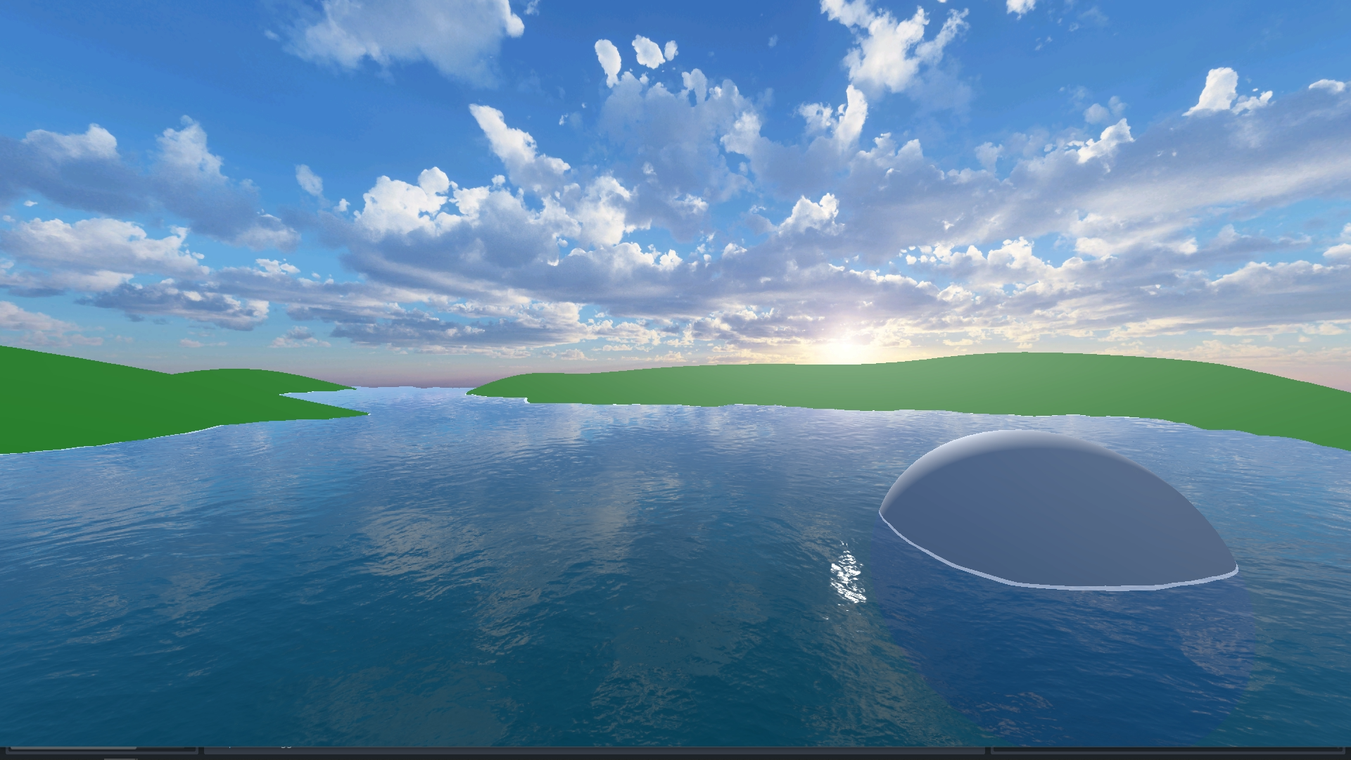
FINAL STEPS
The shader itself is complete and you can add it into any terrain scene or level you have. The tutorial demo project contains simple procedural terrain built with the same vertex displacement as the water and a WorldEnvironment with a high quality panoramic image for the sky. You can find both of those setup within the tutorial project files.